Printed Circuit Board Manufacture

Printed Circuit Boards

In our series on Electronics Design we have looked at the Electronics Design Process from Requirements Capture, Technology Selection, Component Selection, Schematic Capture and finally PCB Design of the  Printed Circuit Board including PCB Layout. Now we have a design and the Electronics CAD files to make a Prototype.

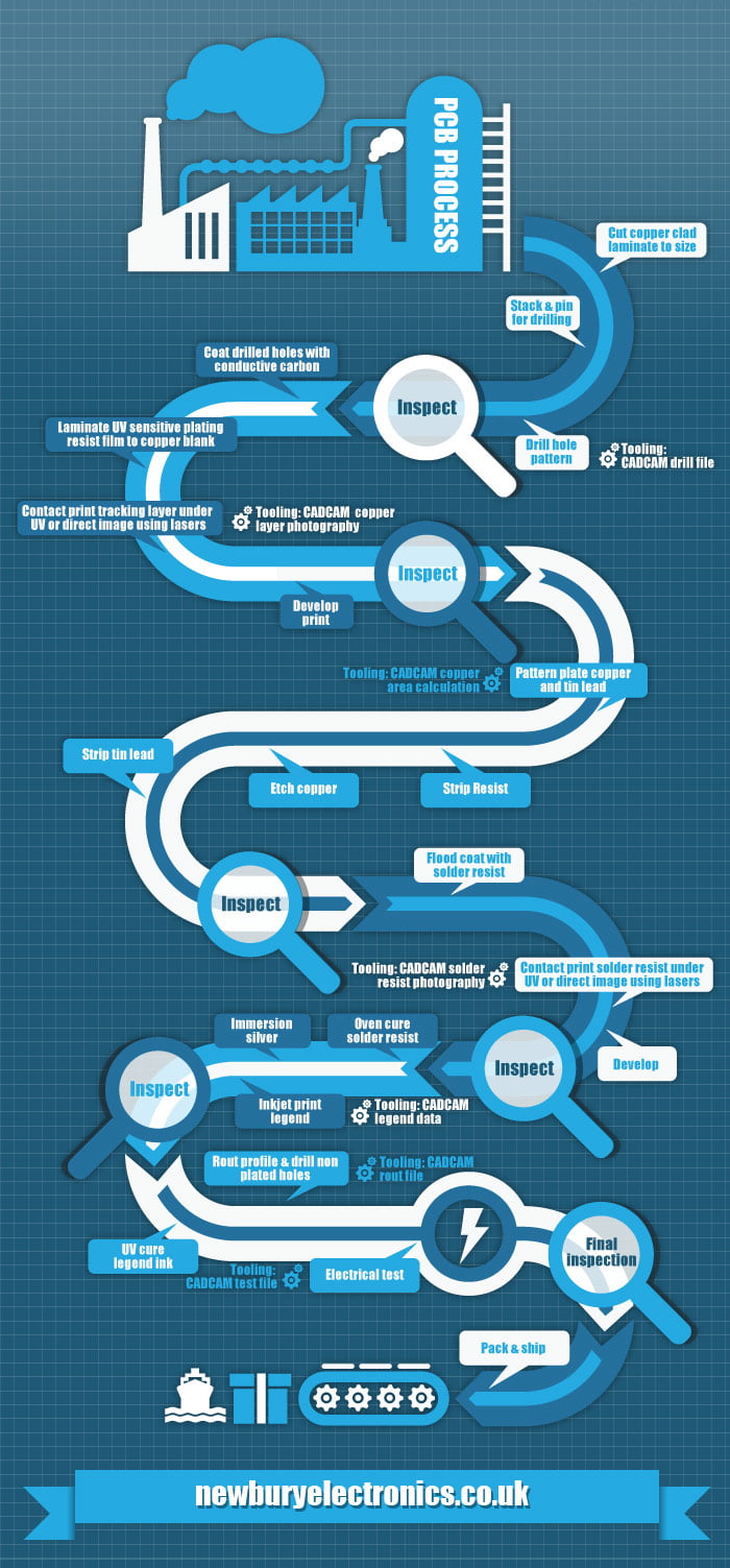
There are a number of steps involved in making a PCB and the following infographic provides an overview.

PCB Manufacture Steps

PCB Manufacture Steps

This infographic is courtesy of Newbury Electronics.


PCB Manufacturing Problems

That is a lot of steps. And there are things that can go wrong. The main pitfalls to avoid in the PCB Design Process are:

  • track widths too narrow
  • clearances between tracks are too small
  • acute angle entry to pads
  • component footprints have pins in the wrong place or the wrong size
  • component outlines are wrong
  • silkscreen or overlay over solder pads
  • via annulus too thin
  • mounting holes in the wrong place or the wrong size
  • PCB outline incorrect
  • PCB 3D profile doesn’t fit into the intended enclosure

And there are a range of issues that can affect the PCB Manufacturing Process. These include:

  • misalignment of drill holes to tracks to PCB outline routing
  • internal cut outs missed / not routed
  • over etching or under etching of the copper
  • incomplete plated through holes
  • poor surface finish
  • poor FR4 and copper bonding or moisture ingress leading to de lamination

Maybe you are wondering how a PCB ever gets made successfully? This comes back to undertaking the PCB Design with an understanding of both electronics engineering design principles and the process capability of the manufacturer into account. And when you get it right, the final product can be pretty awesome. A good example can be found at this post about making a Fine Pitch PCB.

RGB LED Array Close Up

RGB LED Array Close Up

Next we will look at the PCB Assembly process.

Successful Endeavours specialise in Electronics Design and Embedded Software Development. Ray Keefe has developed market leading electronics products in Australia for nearly 30 years. This post is Copyright © 2015 Successful Endeavours Pty Ltd.

Electronics Design: PCB Layout

PCB Layout

After the Schematic Capture component of the Electronics Design  is complete, the logical connections for the electronics components have been determined. If the Electronics CAD package also supports it, you can add rules to guide the Printed Circuit Board Layout, also abbreviated to PCB Layout which we will use from here on.


The PCB provides both the mechanical support for the components and is many cases is a critical part of the circuit since the length of tracks, their thickness, their clearance from other tracks and the relative placement of components and tracks can significantly influence the final performance of the PCB. This is particularly true as power levels, clock speeds or frequency increases.


The Electronic Schematic defines the electrical connections between components, the value of components such as resistors, capacitors and inductors, the type of semiconductors used (silicon chips) and the connectors that take signals and power on and off the PCB. Each item on the schematic has to be linked to a physical shape that will go onto the PCB. This is done by assigning a footprint to the schematic item.


Schematic Symbol

I will explain  it works. The Schematic Symbol for an FT232RL USB Serial Interface device is shown below. This is arranged with the signals conveniently placed to suit logical connections and to make the overall Schematic easy to read and understand.  The signal name is shown inside the symbol boundary, and the pin number of the IC package is shown on the outside.
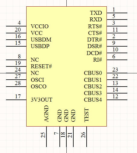
 

FT232RL Schematic Symbol

FT232RL Schematic Symbol

Schematic Circuit

So this  is the symbol for a single part, an IC or Integrated Circuit. The Schematic Circuit or Electronic Schematic shows the connections to the other parts of the circuit. Below we see USB connector wired up the the FT232RL IC and the power supply bypass capacitors. The logic level UART signals are shown at the top right. This section of the Electronic Schematic provides the logical connections for a USB serial interface.
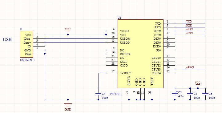
 

FT232RL USB Schematic

FT232RL USB Schematic

PCB Footprint

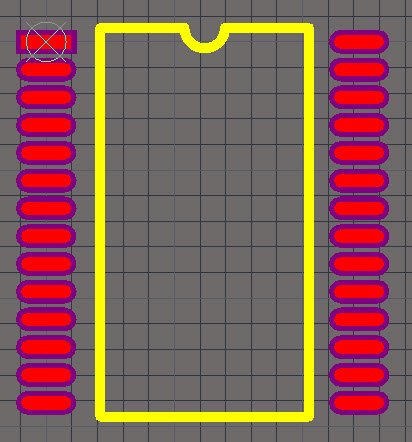
Before we can do the PCB Layout, we have to associate the PCB Footprint each Schematic Symbol will use. The PCB Footprint for the FT232RL IC is shown below.
 

FT232RL PCB Footprint

FT232RL PCB Footprint


This is one of the 2 possible footprints for the FT232RL. This one is a 28 pin SSOP package.


Once each Schematic Symbol has a PCB Footprint, we are ready to do the PCB Placement.


PCB Placement

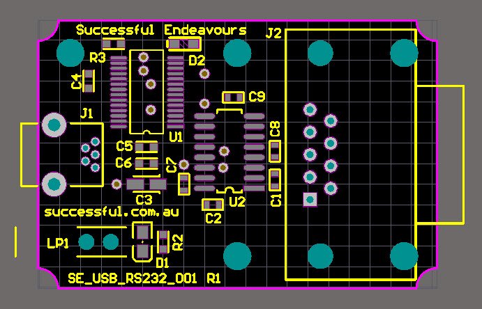
The first step is to create the outline for the PCB and its mounting points, then to place each PCB Footprint so it is in the correct place. For some components, such as connectors, there is a specific place it must go. For other components, there is more freedom to choose the position and there are groups of components that must be in a specific relationship to each other. An example of this are the power supply bypass capacitors which must go very near to the IC they are supporting.


An example of a completed PCB Placement is shown below. This is a USB to RS232 serial converter.
 

PCB Unrouted

PCB Unrouted

PCB Routing

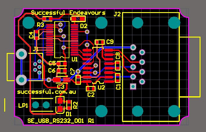
Now we have the components where we want them, we turn on the auto-router and the PCB is finished. Sorry but I couldn’t help that. The auto-routing features of most PCB Layout CAD software packages are never as good as doing it yourself. They can be useful for testing the ease of routing for a particular placement. There are a lot of manufacturing considerations that need to be taken into account and track size requirements, either for current carrying or voltage drop, can be hard to define from just the schematic. And example of this is the main system voltage such as VCC. In some parts of the circuit the required current is low so smaller track sizes are OK, whereas other areas need heavier tracks. It isn’t easy to define this at the schematic level because they are all the same signal or Net.


The PCB with the routing complete is shown below. The selection of track size is related to the current the circuit needs to carry. A good reference for determining the track size is provided by the standard IPC-2222A.
 

PCB Routed

PCB Routed

PCB 3D Cad Integration

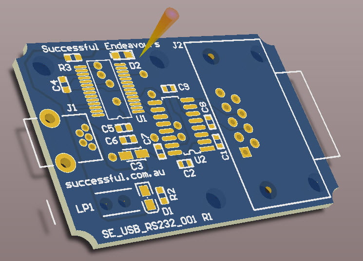
It is also important to make sure the PCB will fit into a mechanical enclosure. Most modern PCB CAD tools, such as Altium Designer which we use, can create full 3D models of the PCB. Shown below is an example of just the PCB without the components showing.
 

3D PCB View

3D PCB View


So there we have it. A PCB taken from the completed Electronic Schematic through to a PCB Layout.


Next we will look at prototyping our new PCB.


Successful Endeavours specialise in Electronics Design and Embedded Software Development. Ray Keefe has developed market leading electronics products in Australia for nearly 30 years. This post is Copyright © 2015 Successful Endeavours Pty Ltd.

PCB Design For Manufacture

Design For Manufacture

Electronics products almost invariably have a Printed Circuit Board , PCB, on the inside. This is one of the most common things we do, designing the Printed Circuit Board on the inside on the product. Now designing a Printed Circuit Board so it works correctly is one thing, but if you are going to make them cost effectively in volume then you have to consider the manufacturing options at your disposal. To achieve Low Cost Electronics Manufacture requires every aspect of the design to be considered.

PCB Roach - an example of technology art

PCB Roach – an example of technology art

So the things to focus on are:

  • Use SMT as much as possible,
  • Reduce the number of components by using more highly integrated circuits,
  • Reduce the variety of components so the number of reels is reduced,
  • Ask the PCB loader about their standard panel sizes. If you can adjust the PCB size to suit them then it will reduce their costs,
  • Work with component types that the PCB loader can handle
  • Work with components that you can buy in suitable quantities

Ray Keefe has been developing high quality and market leading electronics products in Australia for nearly 30 years. For more information go to his LinkedIn profile at Ray Keefe. This post is Copyright © 2011 Successful Endeavours Pty Ltd.

The Future of Low Cost Electronics Manufacture

High End Electronics

In the early days Electronics was hand wired on a chassis. Some high end valve amplifiers still do this.


But of course this isn’t very compact. For those who didn’t know, I am a guitarist and use a Carvin MTS3212 Master Tube Series tube amplifier which I still enjoy very much. So when compact isn’t a priority and cost isn’t as important as the sound, then you go for this sort of amplifier. This is another example of the trade-offs we discussed in the Project Priorities Perspective where it’s about Performance and Cost is the lowest priority.


Low Cost Electronics Manufacture

For Low Cost Electronics Manufacture however, there are other factors that come into play. You want quality and you want it in a timely manner but the cost has to be low so that you have a decent profit margin. So hand wiring is out because that is expensive.


Very well designed Printed Circuit Board PCB can produce excellent results and with the move to Surface Mount Technology SMT and the Surface Mount Device SMD the Component Loading Cost is also reduced as components are put in place by machines and there are no leads or tails to trim after soldering. So this really helps with Electronics Manufacturing Cost and for at least the next little while will remain the way to go.


Another strategy for reducing cost is to use a modern Integrated Circuit IC because you can fit more functions into a more complex device and although it sometimes costs more for that individual device, you can reduce cost by removing other devices, reducing size and reducing loading and handling costs.


Reducing size reduces cost because you get more Printed Circuit Boards on a Panel and the cost of a panel in general is roughly the same regardless of how many PCBs there are on it.


Emerging Electronics Technologies

But the future is approaching and there are some very interesting developments under way. These involve Organic Semiconductors and Printable Electronic Circuits. Check out the following links:


printable electronics – a game changer


printable electronics on the rise


printable electronics to surpass $7 billion in 2010


Organic Semiconductors


I was particularly interested in the idea that the number one piece of equipment purchased by universities and Research and Development corporations conducting Electronics Research would be an inkjet printer! And did you notice the convergence between these two Low Cost Electronics Technologies?


We are in for interesting times indeed when you can design your circuit and then prototype it on your printer.


Ray Keefe has been developing high quality and market leading electronics products in Australia for nearly 30 years. For more information go to his LinkedIn profile. This post is Copyright © Successful Endeavours Pty Ltd.

Analogue Electronics – a Surprising Way to Extend Battery Life

Today we look at one of the Project Priorities Perspectives in action. This was a case where performance was the most important factor and so minimising cost or time to market was a lower priority in the this Electronics Manufacture project. In this case the PCB and electronics were Manufactured In Australia.


We were developing a wireless Data Logger product. We selected 802.15.4 as the wireless protocol but did not need the interoperability of ZigBee. A key issue here was Battery Life. One use of the product was as a device left in the field and collected after 1 to 6 months. The actual time interval depended on the use. Since we have the client’s permission we can share details of the project and the product with you.


The product is a Corrosion Protection Data Logger and the client is Borgtech. The first version is the Borgtech CPL2 and it is on the market today.


Some key product features made it a little tricky as an Electronics Design Project:

  • inputs must withstand lightning strike impulses. This equated to 5KV for 2 seconds according to the local standards!
  • wireless connection for both convenience and also as an OH&S safety measure
  • 6 months battery life
  • 60dB rejection of mains frequencies at 50Hz and 60Hz
  • 10MOhm input impedance
  • a good profit margin

Don’t worry if you don’t understand what all the details mean, I wanted to show how we used the process to identify the best approach rather than go further into millivolts and microwatts.


Technically, this project was quite a challenge. And a classic niche marketing example as well. My initial approach was to minimise the production component cost and look at ways to meet the other objectives. But it didn’t take long to realise that battery life was going to be the hardest challenge here. I was able to use digital signal processing techniques (software) to meet the mains frequency rejection but the power requirements meant we were never going to get 6 months battery life and the radio side also contributed to that problem. I’ll concentrate on the filtering problem.

Analogue Electronics to the rescue

Normally we have been removing electronics components and replacing them with software to save on product cost. But this time, the priority was performance and not cost. So I added components instead. Below is a schematic representing the front end of the product.

schematic

Analogue Electronics Schematic

For those interested, this is a twin T filter. It is a notch filter that takes out specific frequencies. If you want more details then post a comment and I’ll add them.


The great thing about this is that it doesn’t use any Battery Power. Unlike the software solution which uses the whole power budget on its own. So from the batteries perspective, it is FREE! It did cost some design effort and did add some production cost but the battery got off lightly.


So here is how the priorities played out for this project. To get the performance, it cost a bit more and took a bit longer. The outcome was the right product at an acceptable price point and in a market with growing demand. Powerful stuff.


Now we did have to do a lot of other stuff to deliver this product so that it met every one of the design objectives. It also delivered on the client’s expectations and met the cost target too. It helped a lot that Borgtech understood their market and were able to guide us when making the decisions about priorities.


In practice, we make decision like the one above every day. Going left at the right time when everyone else is going right can deliver outstanding results. Marc Dussault refers to this as antimimeticisomorphism.


Next I want to look at going the opposite way to the path we took for this project. This is a case where cost is king and performance must be good enough but is not the primary priority.


Ray Keefe has been developing high quality and market leading electronics products in Australia for nearly 30 years. For more information go to his LinkedIn profile. This post is Copyright © Successful Endeavours Pty Ltd.