
3D Printing
3D Printing has been a big topic for some time. It works in a number of different ways and you can print in metals, plastic or paper. For this post, I will focus on FDM or Fused Deposition Modelling. It is also a method within the general area of Additive Manufacturing.
We work with a wide range of Mechanical Engineering and Industrial Design companies and I had expected them to all be right into 3D Printing. But I was wrong. So we decided to do it ourselves. Here is what we were looking for:
- cost under $5K
- more than 1 filament material type
- readily available filament (overnight delivery preferred)
- 0.1mm resolution
- fully enclosed
- can run stand alone (you don’t need to have it permanently connected to a computer)
- automatic material detection
- upgradable nozzles and software
What we ended up selecting did all of the above but the price point was under $2K! The unit is an Automaker from Robox.

CEL-Robox Automaker
3D Printer Application
So after making a few of the sample models that came with the unit, it was time to start using it in a real project. One set of negatives about 3D Printing is that it is slow and noisy. So even though we selected a fully enclosed unit, it was still too noisy to sit in the middle of the office. So we relocated it to the workroom where we do the more mechanical tasks. We also had to decide how we would create 3D Models. So lets go through the whole process.
For the project, we needed a custom spacer for a 4-20mA current output voltage sensor. We were redesigning a product that had gone obsolete. Our client only needed 50 of them to replace failed units in the field and for spares over time. Having designed the Printed Circuit Board we now needed a spacer that would allow us to use an insulated case TO220 NPN transistor in place of a TO3 NPN Transistor.
3D Model Creation
The first step is to create a 3D Model of the shape we needed. This turned out to be much easier than we expected. We don’t do mechanical CAD in house so we elected to try an online tool. The tool we selected is TinkerCAD. It works in your browser and you can download an STL file which is the format most 3D Printers can use.

TinkerCAD online 3D Design
The software works by letting you add shapes together to make an object. You can also turn any shape into a hole. And you can set the height and location of any object including its elevation. This was more than enough to handle this project. Above is a screenshot of the completed model. We then downloaded it and fed it into the CEL-Robox 3D Printer.
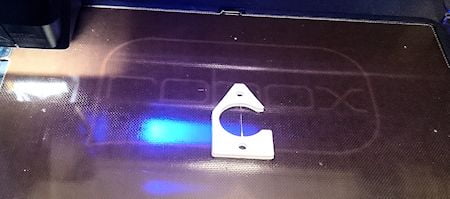
3D Printing in Action
This is a small part and only took 12 minutes to print.
3D Printed Spacer
So now we have our Custom Electronics Spacer. And at a small fraction of the time and cost of getting it drawn up mechanically and made by someone else.
Electronics Prototype
Time to assemble the PCB and make sure everything is OK.

3D Printed Spacer Fitted
This is perfect. Now we can get to testing the new design and hand it over to our client for them to evaluate and approve.
3D Printing Creates New Opportunities
Having done this one exercise, I can see enormous possibilities for this technology at Successful Endeavours. Not only can it save time and cost like it did for this project, but it allows us to do new things we might not have tried before. For lower volume products, you can afford the tooling for custom injection moulded parts, but now we don’t need to.
This is really going to be much better than I thought.
Successful Endeavours specialise in Electronics Design and Embedded Software Development. Ray Keefe has developed market leading electronics products in Australia for nearly 30 years. This post is Copyright © 2015 Successful Endeavours Pty Ltd.