Fine Pitch Printed Circuit Board
This example is from a project coming to the end of the Proof of Concept phase. So we have done the Electronics Design and also completed the PCB Layout. I can’t tell you what it does, but you don’t really need to know in order to appreciate the technology. This is an example of a Fine Pitch PCB or Fine Pitch Printed Circuit Board. And even better, it was made right here in Melbourne, Australia.
Pictures first.
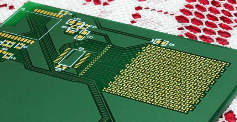
Above we have the top surface of a Prototype PCB that drives a 16 x 16 or 256 RGB LED array. The size is 25mm square for the LED Array. You might also have realised that this is a custom RGB LED display. The display is driven as a row x column matrix. This top side has the 16 row drivers.
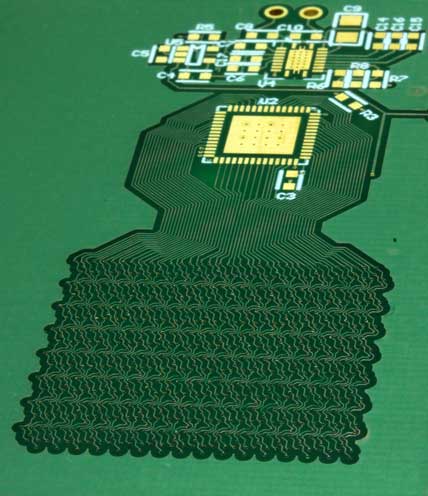
This is the underside with the 16 x 3 = 48 column drivers.
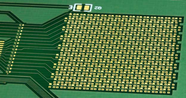
This shows some more detail where the Sea of RGB LEDs is sitting. They are in a staggered offset to reduce jagged edges on the image when it is displayed.
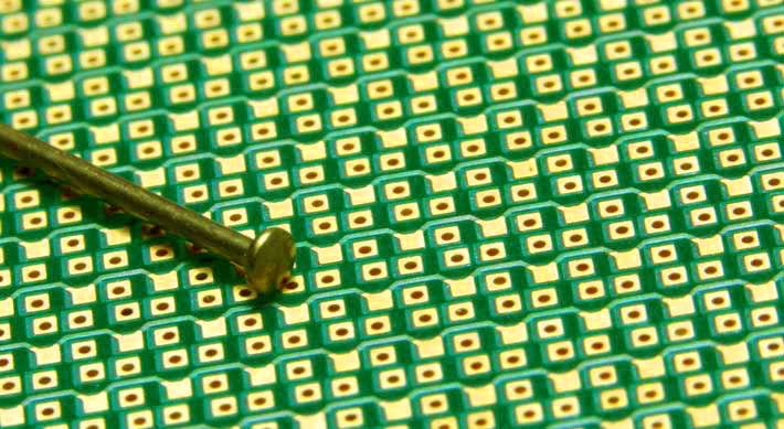
This final picture is a close up of the RGB LED array with a lace pin as a size reference. The RGB LEDs are 1mm wide and the pin head is a bit less than 1mm across. This is the smallest pin I could find.
Fine Pitch PCB Technology
Now for some technical details:
- 4 mil track width (that is 0.1 mm)
- 4 mil clearance (that is also 0.1 mm)
- 0.25 mm via hole diameter
The Prototype PCB was manufactured by PCB Fast. We used them for our Prototype PCBs because they manufactured in Australia. And that is part of our focus, maintaining manufacturing in Australia. So I was very impressed with the work they did and thought this was a great way to show what they can do. I was also impressed with the spirit of adventure Kevin and Leeanne had in taking this one on.
One day I’ll be able to tell you what it was for.
Successful Endeavours specialise in Electronics Design and Embedded Software Development. Ray Keefe has developed market leading electronics products in Australia for nearly 30 years. This post is Copyright © 2015 Successful Endeavours Pty Ltd.


Thanks for the showcase Ray.
Normally we limit the track work to 5 mil track and clearance. But pushing the process to 4 mil worked well, it was good to have the opportunity to put theory to practice on a live project.
Thanks again,
Kevin.
Hi Ray,
A close-up shot of the ‘rear’ via tracks would also have been interesting – that’s a real chunk of spaghetti!
Nice work.