Printed Circuit Board Manufacture

Printed Circuit Boards

In our series on Electronics Design we have looked at the Electronics Design Process from Requirements Capture, Technology Selection, Component Selection, Schematic Capture and finally PCB Design of the  Printed Circuit Board including PCB Layout. Now we have a design and the Electronics CAD files to make a Prototype.

There are a number of steps involved in making a PCB and the following infographic provides an overview.

PCB Manufacture Steps

PCB Manufacture Steps

This infographic is courtesy of Newbury Electronics.


PCB Manufacturing Problems

That is a lot of steps. And there are things that can go wrong. The main pitfalls to avoid in the PCB Design Process are:

  • track widths too narrow
  • clearances between tracks are too small
  • acute angle entry to pads
  • component footprints have pins in the wrong place or the wrong size
  • component outlines are wrong
  • silkscreen or overlay over solder pads
  • via annulus too thin
  • mounting holes in the wrong place or the wrong size
  • PCB outline incorrect
  • PCB 3D profile doesn’t fit into the intended enclosure

And there are a range of issues that can affect the PCB Manufacturing Process. These include:

  • misalignment of drill holes to tracks to PCB outline routing
  • internal cut outs missed / not routed
  • over etching or under etching of the copper
  • incomplete plated through holes
  • poor surface finish
  • poor FR4 and copper bonding or moisture ingress leading to de lamination

Maybe you are wondering how a PCB ever gets made successfully? This comes back to undertaking the PCB Design with an understanding of both electronics engineering design principles and the process capability of the manufacturer into account. And when you get it right, the final product can be pretty awesome. A good example can be found at this post about making a Fine Pitch PCB.

RGB LED Array Close Up

RGB LED Array Close Up

Next we will look at the PCB Assembly process.

Successful Endeavours specialise in Electronics Design and Embedded Software Development. Ray Keefe has developed market leading electronics products in Australia for nearly 30 years. This post is Copyright © 2015 Successful Endeavours Pty Ltd.

Electronics Design: PCB Layout

PCB Layout

After the Schematic Capture component of the Electronics Design  is complete, the logical connections for the electronics components have been determined. If the Electronics CAD package also supports it, you can add rules to guide the Printed Circuit Board Layout, also abbreviated to PCB Layout which we will use from here on.


The PCB provides both the mechanical support for the components and is many cases is a critical part of the circuit since the length of tracks, their thickness, their clearance from other tracks and the relative placement of components and tracks can significantly influence the final performance of the PCB. This is particularly true as power levels, clock speeds or frequency increases.


The Electronic Schematic defines the electrical connections between components, the value of components such as resistors, capacitors and inductors, the type of semiconductors used (silicon chips) and the connectors that take signals and power on and off the PCB. Each item on the schematic has to be linked to a physical shape that will go onto the PCB. This is done by assigning a footprint to the schematic item.


Schematic Symbol

I will explain  it works. The Schematic Symbol for an FT232RL USB Serial Interface device is shown below. This is arranged with the signals conveniently placed to suit logical connections and to make the overall Schematic easy to read and understand.  The signal name is shown inside the symbol boundary, and the pin number of the IC package is shown on the outside.
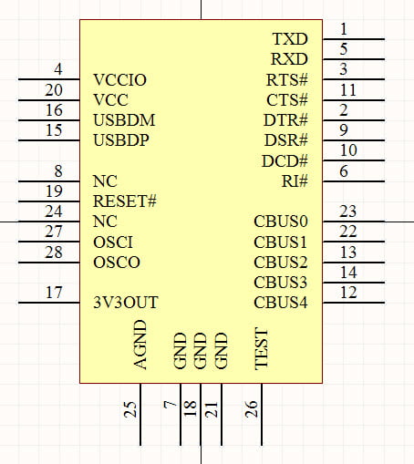
 

FT232RL Schematic Symbol

FT232RL Schematic Symbol

Schematic Circuit

So this  is the symbol for a single part, an IC or Integrated Circuit. The Schematic Circuit or Electronic Schematic shows the connections to the other parts of the circuit. Below we see USB connector wired up the the FT232RL IC and the power supply bypass capacitors. The logic level UART signals are shown at the top right. This section of the Electronic Schematic provides the logical connections for a USB serial interface.
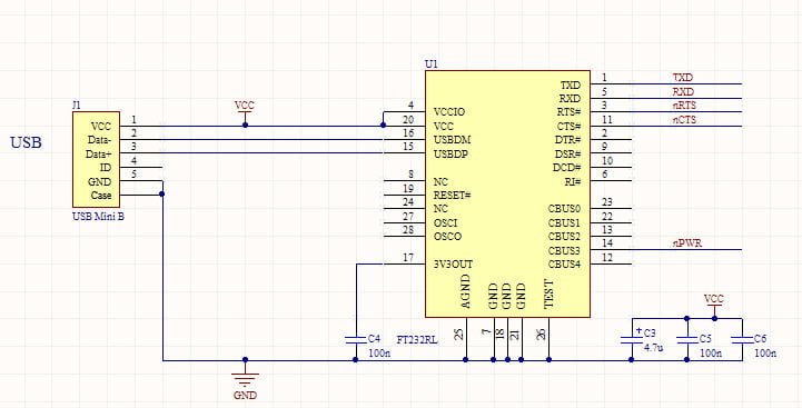
 

FT232RL USB Schematic

FT232RL USB Schematic

PCB Footprint

Before we can do the PCB Layout, we have to associate the PCB Footprint each Schematic Symbol will use. The PCB Footprint for the FT232RL IC is shown below.
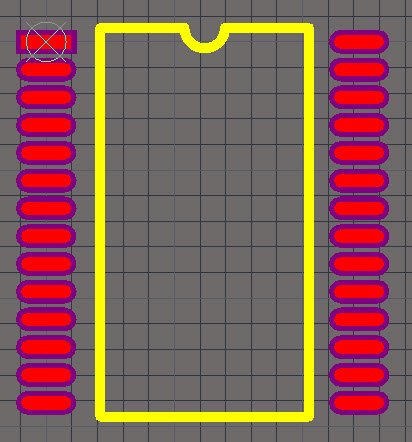
 

FT232RL PCB Footprint

FT232RL PCB Footprint


This is one of the 2 possible footprints for the FT232RL. This one is a 28 pin SSOP package.


Once each Schematic Symbol has a PCB Footprint, we are ready to do the PCB Placement.


PCB Placement

The first step is to create the outline for the PCB and its mounting points, then to place each PCB Footprint so it is in the correct place. For some components, such as connectors, there is a specific place it must go. For other components, there is more freedom to choose the position and there are groups of components that must be in a specific relationship to each other. An example of this are the power supply bypass capacitors which must go very near to the IC they are supporting.


An example of a completed PCB Placement is shown below. This is a USB to RS232 serial converter.
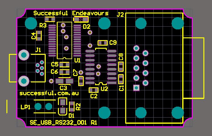
 

PCB Unrouted

PCB Unrouted

PCB Routing

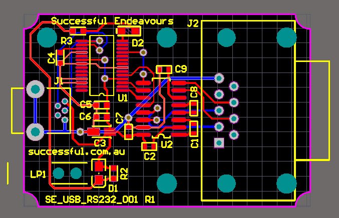
Now we have the components where we want them, we turn on the auto-router and the PCB is finished. Sorry but I couldn’t help that. The auto-routing features of most PCB Layout CAD software packages are never as good as doing it yourself. They can be useful for testing the ease of routing for a particular placement. There are a lot of manufacturing considerations that need to be taken into account and track size requirements, either for current carrying or voltage drop, can be hard to define from just the schematic. And example of this is the main system voltage such as VCC. In some parts of the circuit the required current is low so smaller track sizes are OK, whereas other areas need heavier tracks. It isn’t easy to define this at the schematic level because they are all the same signal or Net.


The PCB with the routing complete is shown below. The selection of track size is related to the current the circuit needs to carry. A good reference for determining the track size is provided by the standard IPC-2222A.
 

PCB Routed

PCB Routed

PCB 3D Cad Integration

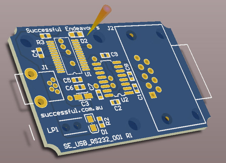
It is also important to make sure the PCB will fit into a mechanical enclosure. Most modern PCB CAD tools, such as Altium Designer which we use, can create full 3D models of the PCB. Shown below is an example of just the PCB without the components showing.
 

3D PCB View

3D PCB View


So there we have it. A PCB taken from the completed Electronic Schematic through to a PCB Layout.


Next we will look at prototyping our new PCB.


Successful Endeavours specialise in Electronics Design and Embedded Software Development. Ray Keefe has developed market leading electronics products in Australia for nearly 30 years. This post is Copyright © 2015 Successful Endeavours Pty Ltd.

Fine Pitch PCB

Fine Pitch Printed Circuit Board

This example is from a project coming to the end of the Proof of Concept phase. So we have done the Electronics Design and also completed the PCB Layout. I can’t tell you what it does, but you don’t really need to know in order to appreciate the technology. This is an example of a Fine Pitch PCB or Fine Pitch Printed Circuit Board. And even better, it was made right here in Melbourne, Australia.


Pictures first.


RGB Light Emitting Diode Array

RGB Light Emitting Diode Array

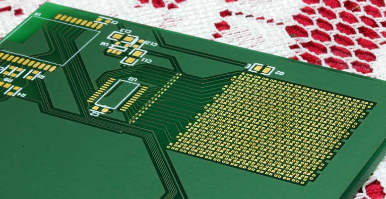
Above we have the top surface of a Prototype PCB that drives a 16 x 16 or 256 RGB LED array. The size is 25mm square for the LED Array. You might also have realised that this is a custom RGB LED display. The display is driven as a row x column matrix. This top side has the 16 row drivers.


RGB LED Array Bottom Side

RGB Light Emitting Diode Array Bottom Side

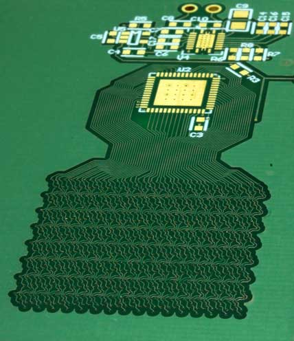
This is the underside with the 16 x 3 = 48 column drivers.


RGB LED Array Detail

RGB LED Array Detail

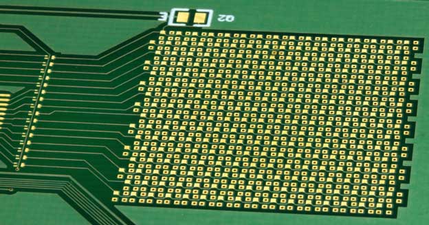
This shows some more detail where the Sea of RGB LEDs is sitting. They are in a staggered offset to reduce jagged edges on the image when it is displayed.


RGB LED Arracy Close Up

RGB LED Arracy Close Up

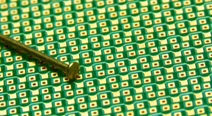
This final picture is a close up of the RGB LED array with a lace pin as a size reference. The RGB LEDs are 1mm wide and the pin head is a bit less than 1mm across. This is the smallest pin I could find.


Fine Pitch PCB Technology

Now for some technical details:


  • 4 mil track width (that is 0.1 mm)
  • 4 mil clearance (that is also 0.1 mm)
  • 0.25 mm via hole diameter


The Prototype PCB was manufactured by PCB Fast. We used them for our Prototype PCBs because they manufactured in Australia. And that is part of our focus, maintaining manufacturing in Australia. So I was very impressed with the work they did and thought this was a great way to show what they can do. I was also impressed with the spirit of adventure Kevin and Leeanne had in taking this one on.


One day I’ll be able to tell you what it was for.


Successful Endeavours specialise in Electronics Design and Embedded Software Development. Ray Keefe has developed market leading electronics products in Australia for nearly 30 years. This post is Copyright © 2015 Successful Endeavours Pty Ltd.

Electronics Design the Next Generation

Electronics Design

Electronics Design is a very challenging area where reducing Time to Market, increasing Engineering Effort, constantly improving technology, tooling lead time and Agile Software Development methodologies all lead to rapidly changing requirements while the project delivery time frame remains immutable. Fortunately Electronics Engineers are up for a challenge.


At Successful Endeavours we use Altium Designer for our Printed Circuit Board Schematic Capture and PCB Layout. So I was amused to see this video clip of some of the typical things that you have to overcome when doing an Electronics Design project. Enjoy.


Ray Keefe has been developing high quality and market leading electronics products in Australia for nearly 30 years. For more information go to his LinkedIn profile. This post is Copyright © 2010 Successful Endeavours Pty Ltd.

Sprechen De Cantonese? – Electronics Design in Australia

There are many companies successfully doing good business in China. Most of them are large, have deep pockets and have core staff in China making sure it stays good. Names like Sony, Siemens, IBM (Lenovo)…


Smaller companies can run into trouble. This is a case study of a project we were able to rescue. I won’t give out technical or commercially sensitive details (we will never do that – in fact we offer an NDA, Non-Disclosure Agreement, to all our clients) but I will look at the overall project and the issues that arose.


For ease of reference, I will refer to the client as Mr Electronics. Mr Electronics had spent a year getting a product developed in China with the ultimate aim of manufacturing it there. Conventional wisdom was on Mr Electronics’ side. Most people believe that it is cheaper to make things in China than here. And the engineering effort was being done for free by the manufacturer. What is not to like about this arrangement? It has both the perceived benefits of making electronics products in China:

  1. low manufacturing cost
  2. low engineering cost

So where is the catch?

Well, you might have noticed that Mr Electronics had spent a year to date on the project. What I didn’t tell you is that it was simple product; conceptually simple and physically simple. It was battery operated and only did one thing. Every time the project was reviewed with the manufacturer and the question was asked if everything was now clear, the answer was “Yes“. Yet every prototype presented clearly showed the answer should have been “Clueless“. They were not speaking the same language! It wasn’t just English versus Chinese, but it was a completely different culture of how to communicate. Since “Yes” is the best answer, it is the only answer you get, regardless of the real situation. Mr Electronics is not alone in having run into this issue.


A year is a long time to not have your product available for sale!

In frustration, Mr Electronics approached us to review the project and advise on how to proceed. The production in this case was going to remain in China (you can’t win them all) since the manufacturer had developed the enclosure and that part looked to be acceptable. So we concentrated on the electronics and software. Within 17 days we had obtained the following outomes:

  1. analysed the specification and recommended changes that doubled the battery life while improving performance
  2. designed the electronics, PCB layout and software
  3. produced a fully working prototype unit for evaluation
  4. generated all the production documentation to make, program and test the PCB (circuit board)

Although I’m proud of the result we got here, my point is that they might have never gone to market if they had stayed on the original path.


So did Mr Electronics have a happy outcome? Not completely!


Mr Electronics isn’t very much out of pocket since the actual cost was low, even for 10,000 units. He is however out nearly 2 years of his life, hasn’t captured the market opportunity he originally aimed at and isn’t enjoying the profit stream he deserved since his product was a good idea and should have been a commercial winner.


Some key take home points for me were:

  1. get the right people involved and you can reduce your time and cost to market
  2. get the right people involved and you can get a better outcome than you can achieve on your own
  3. China might be cheap but that doesn’t guarantee you will get a commercially successful outcome
  4. “Yes” only means “Yes” when you are both speaking the same language

OK, this post looked at what can go wrong. And unfortunately Mr Electronics’ experience is not unique. But from here on I plan to stick to how to make things go right.


Next I will show you our Project Priorities Perspective and how it can help to bring focus and clarity to maximise the commercial outcome.


Ray Keefe has been developing high quality and market leading electronics products in Australia for nearly 30 years. For more information go to his LinkedIn profile. This post is Copyright © Successful Endeavours Pty Ltd.

________________________________________________